Last week we looked at amplitude modulation using 2 oscillators (ring modulation), as well as with an oscillator and a function (wave shaping). This week we will look at frequency modulation with 2 or more oscillators (frequency modulation – FM) or an oscillator and a function (phase distortion – PD). As an oscillator can be considered as a function, one might say that FM and PD are same technique. How they differ is in structure, and how the parametric controls produce timbre change. Patches for this class can be download here: w5fmpd
frequency modulation
FM is structure very similarly to AM/ring modulation. In the simplest form, there are two oscillators: a carrier and a modulator. In both AM and FM, sidebands are created around the carrier frequency. In AM, the sideband frequencies are Fc + Fm and Fc – Fm. In FM, the sideband frequencies are Fc + n * Fm and Fc – n * Fm; where n goes from 0 to ∞ and the number of audible sidebands increase as the depth of modulation increases.
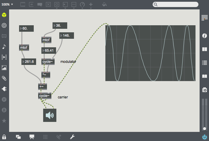 This patch shows 2 oscillator FM synthesis. Both oscillators are sine waves, and one can see the shape of the carrier being deformed as the depth of modulation increases (in the image, the modulation depth is 146). In FM, both carrier and modulator have set frequencies. The output of the modulator is multiplied by the depth of modulation, and this is added to the carrier frequency, If the carrier and modulator frequencies are related by an integer ratio, the sidebands will appear on harmonics of the carrier. One should also note that the modulation depth needs to be increased as the frequency increases so that the amount of frequency deviation is proportional to the carrier frequency.
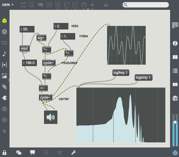 In this example, the previous patch is given new parameters. Now the modulator frequency is expressed by the ratio of the modulator frequency to the carrier frequency and the modulation depth is expressed by the ratio of modulation depth to modulator frequency (index). Ratio and index are much more sensible and powerful controls for FM synthesis. In this patch you can hear the number of audible sidebands increase quickly as the index increases. The spectral sparse-ness increases dramatically as the ratio increases, and a non-integer ratio results in sidebands which are not necessarily related to the fundamental. This patch shows the power of FM, many timbres can be created with only 2 oscillators and 3 parameters.
 As the index increases, one should also note that harmonics will be reflected around 0Hz and the nyquist rate. Reflection around 0Hz will give additional inharmonicity when the ratio is non-integer. When the ratio is an integer, the reflected or wrapped sidebands will land on harmonics and add to the non-wrapped sidebands. Reflection around the nyquist rate is undesirable, as the timbre will become dependent on the sample rate frequency. One trick before we move on – a very high index (over 10,000) can turn an FM oscillator pair into a tunable noise generator. Related to this is the patch on the right, in which the two oscillators are modulating each other, so that each oscillator is both carrier and modulator. By varying the frequencies and indices, one can produce many types of chaotic and unpredictable noise.
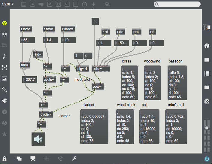 In my final FM patch, I have implemented some of the FM examples that John Chowning developed when he was creating the technique of FM synthesis. In this patch, the index is modulated over the course of a note by an ADSR envelope. A pow~ function is used to give the ADSR a linear (1) or exponential (4) decay. Most of the presets sound better with a linear decay, the final two (a bell, and my version of a bell) sound better with an exponential decay. My bell preset was developed by matching the loudest harmonics of an actual bell, some of which are generated with wrapped sidebands.
FM has been extended much further than John Chowning’s original work. Some of the work involves greater control of the spectrum by using multiple carriers and modulators, mixing aspects of FM synthesis with additive synthesis; adding realistic vibrato in vocal synthesis and using noise sources to simulate breath or bow noise. Many papers in the Computer Music Journal and the proceedings of the International Computer Music Conference detail these developments. The Yamaha DX7 synthesizer patches should also be studied for a thorough knowledge of the technique of FM synthesis.
phase distortion
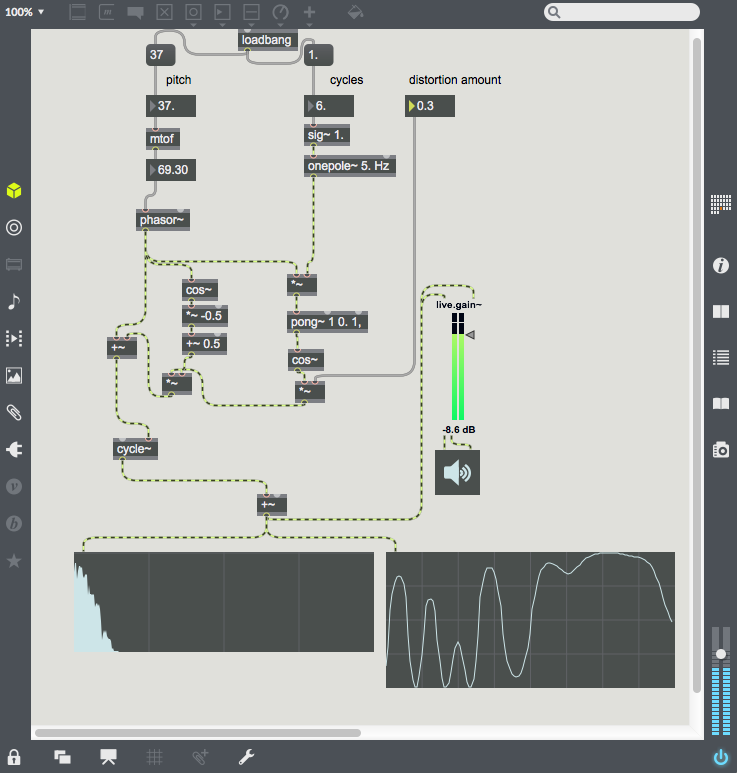 Phase distortion is a technique where the phase is reshaped by a function or through a lookup table to distort the waveform. A sinusoid will be created when the phase distortion function is the identity (let x = x) function; but otherwise the waveform is distorted, adding additional sidebands. Phase distortion is very close to frequency modulation with an integer ratio. In the case of phase distortion, the phase shaping function is cross-faded between the distorted function and an identity function. This has a similar effect to changing the index from maximum to 0 in FM synthesis. In the image on the right is a simple phase distortion patch adds differing numbers of cycles of a cosine wave to the phase. Note that the phase distortion signal is enveloped by a raised cosine so that the beginning and end of the phase is not distorted. Like FM, phase distortion can be developed much further than this example. A good reference example is the Casio CZ-101 synthesizer, which created some very detailed sounds using 2 phase distortion oscillators.