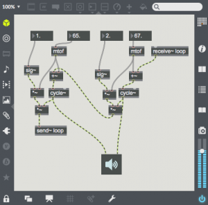
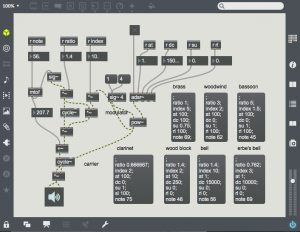
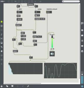
music 176 syllabus – winter 2020

music 176 – custom programming for music – winter 2020

instructor – tom erbe – tre@music.ucsd.edu

thursday: 2 – 5

•••••focus

this quarter we will be learning music DSP programming on bare metal embedded processors with the STM32F processor. to do this we will cover 4 topics.

  1. c/c++ programming
  2. the STM32Fn development environment and SDK
  3. computer music algorithms

••••schedule

as the class is 3 hours long, we will be spending time in each class making sure everyone can recreate the examples on their hardware. bring your laptop, STM development board, earbuds and MIDI keyboard to class.

  1. basics (basics and compilers – setting up a dev environment)
  2. stm 1 – writing embedded code and c rehash
  3. stm 2 – adding sound (first assignment)
  4. dsp code 1 – amplifiers delay and oscillators
  5. dsp code 2 – filters, waveshaping and fm (second assignment)
  6. stm 3 – integrating DSP code into synth framework. MIDI parsing
  7. stm 4 – incorporating files and filesystems (final project assignment)
  8. dsp code 3 – reverb, fft
  9. workshop
  10. class presentation

••••texts – software

these books are very helpful… recommended as reference.

  • C Primer Plus by Stephen Prata
  • Computer Music by Charles Dodge
  • DAFX by Udo Zolzer

•••••my office hours

1-3 tuesday and 10-2 thursday

pm or email me for other hours

tre@music.ucsd.edu

tre@soundhack.com

•••••class requirements

3 projects of increasing complexity…. one is a final project. grad students will be required to use their final project in a piece or for research.

****class notes & assignments

class notes and many examples are on http://synthnotes.ucsd.edu. assignments will be posted on the week assigned.

****example code

additive sawtooth with polyphony – f4disco-midi-saw

same as above with ADSR, 2 oscillator, multiple waveforms, LFO – f4disco-doublesaw

same as above with addition of filters and wave shaping polynomial –f4disco-oscfilt

an example showing sample playback, simple echo and auto-panning – f4disco-sample-echo

7th week example with sample playback and reverb – f4disco-sample-verb

8th week example using compression, timers, ADC – f4disco-sample-timer-mic

9th week example using the LEAF library – f4disco-leaf

MUS206: Hardware Synthesis Syllabus

Hardware Synthesis Syllabus

Topics for Fall 2018

  1. A) Patching and Signals: Control Voltage, Audio, AC, DC, Gates, Triggers (Strange: Chapter 5); B) Slope, Envelope and LFO (Maths Manual – Make Noise Website)
  2. Oscillators: Sine, Square, Triangle and Ramp; Sync; Linear & Log Frequency; Vibrato & Gliss; Subharmonics; Additive; Noise; Multiple Oscillators; ASR (Strange: Chapter 3)
  3. Amplifiers: Tremolo; Envelope and LFO; Amplitude and Ring Modulation, Envelope Tracking, Types of VCAs (Strange: Chapter 4)
  4. Modulation: More Amplitude and Ring Mod, Wave Folding, Frequency Modulation, Chaotic Oscillation, Feedback Networks (Strange: Chapter 7-8)
  5. Playing 1st pieces.
  6. Sequencing and Variation, Structure, Rhythmic Patching, Clocking (Rene Manual – Make Noise Website)
  7. Holiday
  8. Musique Concrete Techniques. Computer Interface: MIDI, Control Voltage, Gates; Recording Material
  9. Reverb and Echo; External Processing; Processing Computer Signals
  10. Playing 2nd pieces

Readings from Allan Strange: Electronic Music; Make Noise Website

Listening Assignments

Pieces Presented on Week 5 and Week 10

MUS271A (Max w6) – delay & filtering

This lesson will cover two fundamental methods in processing sound: delay and filtering. These techniques are related as filtering is based on a mixing a delayed sound with itself. Like all techniques covered in this class, this is only an introduction, there are many more ideas that can be developed beyond the patches presented here. The patches for this lesson can be downloaded here: 03-filters&delay


delay

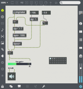
Screen Shot 2018-07-27 at 9.24.41 AMDelay is a method of transmitting sound through a media so that it can be heard later. This media can be magnetic tape, digital memory, or even the air.
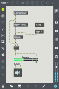
In Max this is done with two objects, tapin~ and tapout~. The audio memory is defined by tapin~, and tapout~ needs to be connected to tapin~ to have it use the tapin~ memory. The argument to tapin~ defines the maximum length of memory, in this patch that is 1000 ms. Both the argument and the input parameter to tapout~ is the delay time. In the case of this patch we are listening to the sound that entered the audio memory 395 ms ago. The tapout~ delay time will be limited to the length of audio memory defined. Any number of tapout~ objects can be connected to a single tapin~ object.


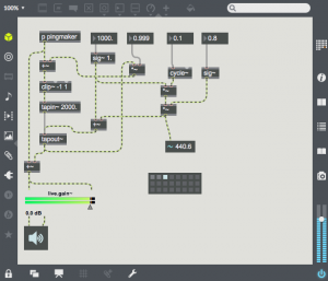
Screen Shot 2018-07-27 at 9.47.59 AMWith many natural acoustic spaces (e.g. in a large room), the delayed sound re-enters the delay after it is heard, and the echo is repeated many times. This repeat can be easily added by sending some of the sound from tapout~ back into tapin~. In this patch, the output is multiplied by a feedback gain of 0.5 and added to the input signal before entering the delay line. This gain represents the gain reduction after each echo. If you select the first preset, you will here multiple decaying echoes. The second preset has much less gain reduction, and is an example of a rhythmic use of delay. The third preset shows the effect of having gain at or above 1.0. The signal soon clips and the delay memory soon fills with distortion. The clip~ object is essential to prevent the volume from getting out of control.


Screen Shot 2018-07-27 at 11.54.52 AMThis next patch shows the simple addition of a sine oscillator as a modulation source for the delay time. When time is modulated, the period of any pitched material in the delay line is expanded and contracted. This will cause doppler pitch shifting effects. The 4 presets show various types of time modulation. The fourth example uses an audio frequency modulation oscillator. This will frequency modulate the contents of the delay memory. Flange, chorus and pitch shifting are all created using carefully tuned time modulation. Try to expand on this patch to create these effects. It will help to use sound sources other than the percussive “pingmaker” subpatch to demonstrate these effects.


to be continued….

MUS271A (Max w5) – modulation 2 (frequency)

Last week we looked at amplitude modulation using 2 oscillators (ring modulation), as well as with an oscillator and a function (wave shaping). This week we will look at frequency modulation with 2 or more oscillators (frequency modulation – FM) or an oscillator and a function (phase distortion – PD). As an oscillator can be considered as a function, one might say that FM and PD are same technique. How they differ is in structure, and how the parametric controls produce timbre change. Patches for this class can be download here: w5fmpd


frequency modulation

FM is structure very similarly to AM/ring modulation. In the simplest form, there are two oscillators: a carrier and a modulator. In both AM and FM, sidebands are created around the carrier frequency. In AM, the sideband frequencies are Fc + Fm and Fc – Fm. In FM, the sideband frequencies are Fc + n * Fm and Fc – n * Fm; where n goes from 0 to ∞ and the number of audible sidebands increase as the depth of modulation increases.

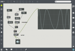
Screen Shot 2018-07-25 at 12.08.51 PMThis patch shows 2 oscillator FM synthesis. Both oscillators are sine waves, and one can see the shape of the carrier being deformed as the depth of modulation increases (in the image, the modulation depth is 146). In FM, both carrier and modulator have set frequencies. The output of the modulator is multiplied by the depth of modulation, and this is added to the carrier frequency, If the carrier and modulator frequencies are related by an integer ratio, the sidebands will appear on harmonics of the carrier. One should also note that the modulation depth needs to be increased as the frequency increases so that the amount of frequency deviation is proportional to the carrier frequency.


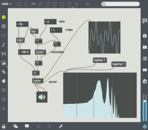
Screen Shot 2018-07-25 at 12.20.35 PMIn this example, the previous patch is given new parameters. Now the modulator frequency is expressed by the ratio of the modulator frequency to the carrier frequency and the modulation depth is expressed by the ratio of modulation depth to modulator frequency (index). Ratio and index are much more sensible and powerful controls for FM synthesis. In this patch you can hear the number of audible sidebands increase quickly as the index increases. The spectral sparse-ness increases dramatically as the ratio increases, and a non-integer ratio results in sidebands which are not necessarily related to the fundamental. This patch shows the power of FM, many timbres can be created with only 2 oscillators and 3 parameters.


Screen Shot 2018-07-25 at 12.42.08 PMAs the index increases, one should also note that harmonics will be reflected around 0Hz and the nyquist rate. Reflection around 0Hz will give additional inharmonicity when the ratio is non-integer. When the ratio is an integer, the reflected or wrapped sidebands will land on harmonics and add to the non-wrapped sidebands. Reflection around the nyquist rate is undesirable, as the timbre will become dependent on the sample rate frequency. One trick before we move on – a very high index (over 10,000) can turn an FM oscillator pair into a tunable noise generator. Related to this is the patch on the right, in which the two oscillators are modulating each other, so that each oscillator is both carrier and modulator. By varying the frequencies and indices, one can produce many types of chaotic and unpredictable noise.


Screen Shot 2018-07-25 at 1.20.59 PMIn my final FM patch, I have implemented some of the FM examples that John Chowning developed when he was creating the technique of FM synthesis. In this patch, the index is modulated over the course of a note by an ADSR envelope. A pow~ function is used to give the ADSR a linear (1) or exponential (4) decay. Most of the presets sound better with a linear decay, the final two (a bell, and my version of a bell) sound better with an exponential decay. My bell preset was developed by matching the loudest harmonics of an actual bell, some of which are generated with wrapped sidebands.


FM has been extended much further than John Chowning’s original work. Some of the work involves greater control of the spectrum by using multiple carriers and modulators, mixing aspects of FM synthesis with additive synthesis; adding realistic vibrato in vocal synthesis and using noise sources to simulate breath or bow noise. Many papers in the Computer Music Journal and the proceedings of the International Computer Music Conference detail these developments. The Yamaha DX7 synthesizer patches should also be studied for a thorough knowledge of the technique of FM synthesis.


phase distortion


Screen Shot 2018-07-25 at 1.51.19 PMPhase distortion is a technique where the phase is reshaped by a function or through a lookup table to distort the waveform. A sinusoid will be created when the phase distortion function is the identity (let x = x) function; but otherwise the waveform is distorted, adding additional sidebands. Phase distortion is very close to frequency modulation with an integer ratio. In the case of phase distortion, the phase shaping function is cross-faded between the distorted function and an identity function. This has a similar effect to changing the index from maximum to 0 in FM synthesis. In the image on the right is a simple phase distortion patch adds differing numbers of cycles of a cosine wave to the phase. Note that the phase distortion signal is enveloped by a raised cosine so that the beginning and end of the phase is not distorted. Like FM, phase distortion can be developed much further than this example. A good reference example  is the Casio CZ-101 synthesizer, which created some very detailed sounds using 2 phase distortion oscillators.

MUS271A (Max w4) – modulation 1 (amplitude)

The next two lessons will focus on techniques which involve reshaping waveforms by modulating a simple (often sinusoidal) waveform. These modulation techniques include:

  • Ring Modulation (aka Balanced Modulation, Amplitude Modulation)
  • Waveshaping
  • Frequency Modulation
  • Phase Distortion

Each type of modulation creates a new waveform that has more harmonic content than the original. The modulating oscillator (or modulator) is connected to either the frequency or amplitude of the audible oscillator (or carrier). Varying the amplitude or frequency changes the slope of the carrier waveform continuously, and this creates new harmonics in the resultant waveform. These new harmonics are called sidebands, as they appear on both “sides” of the carrier frequency – both lower and higher.

Patches for this week are located here: w4rmwsenv. In this case, these patches are starting points – the techniques are developed further in this post. Also included are some simple examples of mixing and envelope usage.

Ring Modulation

This technique is called ring modulation because of the ring of diodes used in the analog implementation of this technique.

Digitally, the technique is much simpler, one simply needs to multiply the amplitude of the carrier oscillator by the output of the modulating oscillator. Here is a simple example:
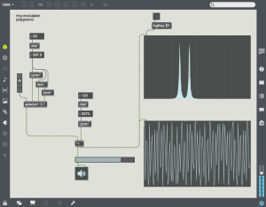
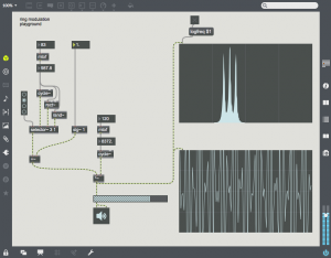
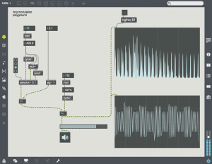
Screen Shot 2018-07-16 at 12.50.14 PMThe carrier is at a fairly high frequency (8372 Hz), and the modulator is at 987.8 Hz. Note that the output consists of two harmonics – one is at C – M (~7384) and the other at C + M (~9360 Hz). These two sidebands are created by the sum and difference of the slopes of the two oscillators. The carrier oscillator is completely absent (this is referred to as “carrier suppression”). One can bring back the carrier by adding an offset to the modulating waveform as in the following patch:Screen Shot 2018-07-16 at 1.00.49 PM
Here a signal of value 1.0 is added to the modulating waveform. This signal is multiplied by the carrier. The carrier then appears in the sonogram in the middle of the two sidebands.

Different signals can be used for the carrier or modulator. In this patch a radio button and selector~ object is used to change the modulator waveform. All the harmonics of the Screen Shot 2018-07-16 at 1.14.46 PMmodulator are now applied to the carrier, giving a much denser waveform. For example, choose the 3rd radio button to use a square waveform. Here one can see all of the harmonics of the square wave on either side of the carrier. Also notice that low sideband harmonics wrap-around 0 Hz, and proceed back upward.Screen Shot 2018-07-16 at 1.21.20 PM
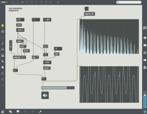
 

Most of the time, ring modulation creates rather dissonant or non-harmonic timbres. This can be limited by relating the frequencies of the carrier and modulator by integers or simple ratios. In this example the carrier is 5/3 the frequency of the modulator.


Single Sideband Ring Modulation (AKA Frequency Shifting)

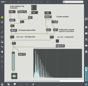
With a little more effort the upper or lower sideband from ring modulation can be suppressed. This technique requires a sine and cosine oscillator pair for the modulating oscillator, and a 90 degree phase shifted version of the carrier.
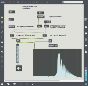
Screen Shot 2018-07-18 at 12.47.10 PMA multiply of sin x sin and cos x cos will create a 180 degree and 0 degree phase shifted components. Adding the two products will leave only the upper sideband. In Max one can use the hilbert~ object to create sin and cos components from any sound source. In this example, a triangle wave is being processed by hilbert~. The frequency of the modulator is the frequency shift of the upper sideband. As the triangle wave is shifted upward, you can hear the harmonics go out of tune, One can also apply SSB ring-modulation/frequency shifting to sound files or live sound sources. At small settings there is still some harmonic integrity, but this soon disappears.
Screen Shot 2018-07-18 at 1.20.47 PMAnother variant of this technique is to use feedback to create a series of harmonics. If the carrier and modulator are related by simple ratios, a consonant timbre is created. Also, as feedback is increased – the gain is increased, so output volume may need to be adjusted to avoid  clipping distortion


Wave Shaping

And speaking of clipping distortion, another form of amplitude processing is wave shaping, a technique in which the original waveform is reshaped by a transfer function. The function is used to map input values to output values and will change the harmonic content of the original waveform.
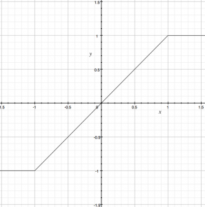
Screen Shot 2018-07-18 at 3.44.47 PMA very typical transfer function is one which produces clipping when the input reaches a limit. In this transfer function, the input value is mapped to the x-axis, and the output on the y-axis. One can think of the input coming in the bottom of the function and the output proceeding out of the right of the function. You can see that when the input goes above 1.0, the output is clipped to 1.0, and similarly the output is clipped to -1.0 for input signals below -1.0. This transfer function is similar to simple amplifier distortion, much like what you would find in a two transistor fuzz pedal. The clipping in this case will add a great number of harmonics to the input signal (aka harmonic distortion). Also note that a steeper slope will produce gain equivalent to the slope.
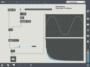
Screen Shot 2018-07-23 at 12.03.10 PMThis transfer function can be implemented in Max with a multiply for the slope between -1.0 and 1.0 and by using pong~ to limit the wave to -1.0 and 1.0. in this case the sine wave is shaped into a sine with the top and bottom flattened. The spectrogram shows the additional harmonics added by this clipping.
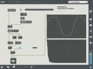
 

Screen Shot 2018-07-23 at 12.18.31 PMThe polynomial “y = 1.5 * x – 0.5 * x^3” can be added to this waveshaper to soften the transition to a clipped waveform. This polynomial causes the slope to decrease as x increases. Any polynomial can be used in Max as a waveshaping function. In this example the polynomial is inserted after the clipping function as the x^3 term will increase rapidly after x passes the -1.0, 1.0 limit.
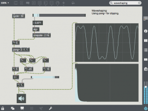
Screen Shot 2018-07-23 at 12.34.56 PMChebyshev polynomials are also often used for waveshaping as they can transform a sine wave into it’s harmonic. This example uses the 5th chebyshev polynomial “y=16x^5 – 20x^3 + 5x. As gain increases from 0.0 to 1.0, the output is reshaped from the fundamental to the 3rd partial to the 5th partial. Multiple chebyshev polynomials can be combined. This type of waveshaping can be very useful when creating tones which have more harmonic content as the amplitude increases.
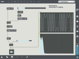
Screen Shot 2018-07-23 at 12.49.38 PMAnother interesting type of wave shaping using half of a cos~ function and the wrap mode (0) of pong~. As the amplitude increases, the sin wave is reshaped through more and more cycles of a cosine function, resulting is a large number of new harmonics. This type of waveshping sounds much like FM synthesis (covered in next week’s lesson).

MUS174C – Editing and Mixing Assignments

Present rough mix/edit week 7 Tuesday
  • 2A: Kjell Nordeson: Farley, D’Agostini
  • 2B: Mari Kawamura: Greenwood, Hess
  • 3A: Madison Greenstone: Bari, Bahn
  • 3B: Kyle Adam Blair: Jiao, Loree
  • 4A: Ben Rempel:  Richardson, Chumakov
Present rough mix/edit week 7 Thursday
  • 4B: Barbara Byers: Levick, Galang
  • 5A: Tim McNalley: Zamora, Reid
  • 5B: Anthony Vine: Abid, Kim
  • 6B: Jordan Morton: Hovander, Jiron

MUS174C – session requirements

Look at the course calendar to see which session you are assigned to.

1) If you are the first person listed in bold, you are responsible for the mic setup, sending me a mic plot and listing the day before the session, checking out microphones, stands, headphones, cables, etc. and setting up the microphones.

2) If you are the second person listed in bold, you are responsible for setting up ProTools before the session (all channels should be created, labelled, and correspond to the mic list from 1. You are also responsible for logging the session.

3) If you are listed for the session, you are helping out in setup and breakout. Also, 1 and 2 can assign you duties (fix the headphones, move the mic, do the log, run the session for a while, make sure no one lets the door slam, etc.)

4) After the session gets started, I will split off with the people who have a session next week to plan that session (in 268). Next week is Greenstone (Tues.) and Blair (Thurs.). If you are listed for either session, you are required to be at the planning meeting.

Tom

MUS174C – Recording Schedule

week 2
4/10: Kjell Nordeson – percussion/vibes set up (Farley, Richardson, Galang, Levick, Loree, Bahn, Zamora)
4/12: Mari Kawamura, piano (Greenwood,ChumakovBahn, Hovander,  Kim, Jiron, Jiao)
week 3
4/17: Madison Greenstone, clarinet  (Hess, Bari, Galang, Loree, D’Agostini, Greenwood,  Zamora, Abid)
4/19: Kyle Adam Blair – musical (Jiao, Loree, Hovander, Richardson, Bari, Jiron, D’Agostini, Hess)
week 4
4/24: Ben Rempel – 4 piece brazilian band   (Kim, Bahn, Galang, Chumakov, Farley, Reid, Zamora, Abid)
4/26: Barbara Byers – voice, koto, percussion, and double bass  (Galang, Zamora, Jiron, Chumakov, Levick, Jiao, Bahn, Greenwood )
week 5
5/1: Tim McNalley – slide guitar trio thingy, guitar/bass/drums (ReidD’Agostini, Hess, Hovander, Bari, Levick, Loree, Greenwood, Abid)
5/3: Anthony Vine – ambient electric guitar and clarinet (Levick, Abid, Reid, Hovander, Chumakov, Richardson, Farley, Kim, Jiron, Jiao)
week 6
5/10: Jordan Morton, voice and bass stuff (Jiron, Hovander, Farley, D’Agostini, Richardson, Bari, Kim, Reid, Hess)

MUS 174C – Syllabus

mus 174c - audio studio techniques - spring 2018
cpmc 269/203 - tuesday, thursday 11:00 - 12:20
instructor - tom erbe - tre@ucsd.edu - cpmc 254
teaching assistant - jordan morton - jmmorton@ucsd.edu

advanced projects – studio design

topics

  • projects in class – working with grad students and faculty guests
  • room acoustics
  • building a studio
  • audio electronics

texts

  1.  tape op magazine www.tapeop.com
  2.  bartlett & bartlett – practical recording techniques

class requirements

  • 25% – attendance, participation, quiz
  • 75% – final project

project requirements

  • tracked in class, each person has specific tasks for tracking session
  • edited as group
  • each person mixes and masters their own version
  • you must help on 4 tracking sessions
  • you must plan and setup a solo session alone, or plan and setup a multiple instrument session with another student
  • must attend planning session before each of 4 selected tracking session
  • show respect for diverse music

classnotes


MUS 174C – Schedule

week 1
4/3: Introduction: Review of general micing techniques/session planning and process
4/5: Planning for week 2 – 6 sessions
week 2
4/10: Kjell Nordeson – percussion/vibes set up
4/12: Mari Kawamura, piano (s)
week 3
4/17: Madison Greenstone, clarinet – extended technique 20′ long piece, very beautiful and interesting and will be a good challenge to mic (s)
4/19: Kyle Adam Blair – demo of a new musical he is writing, w/singers
week 4
4/24: Ben Rempel – 4 piece brazilian band
4/26: Barbara Byers – trio of original music, voice, koto, percussion, and double bass
week 5
5/1: Tim McNalley – alum returning in style with a slide guitar trio thingy, guitar/bass/drums
5/3: Anthony Vine – ambient electric guitar and clarinet, long-form meditative stuff
week 6
5/8: Lecture: Studio Acoustics/Treatment/Room Design
5/10: Jordan Morton, voice and bass stuff, probably live (s)
week 7
5/12: Listening: week 2, 3, 4 play edited rough mixes with critique
5/14: Listening: week 4, 5, 6 play edited rough mixes with critique
week 8
Lecture: Designing a studio of any size (1)
Lecture: Designing a studio of any size (2)
week 9
Lecture: Studio electronics (1)
Lecture: Studio electronics (2)
week 10
Tuesday/Thursday: present final pieces